


Urea Production Line (200,000–800,000 t/y)
Complete urea production system utilizing total recycle, ammonia stripping and CO₂ stripping processes for high-efficiency prilled urea production
The urea production line is a complete urea production system designed for the efficient conversion of ammonia (NH3) and carbon dioxide (CO2) into high-quality urea. The production system supports multiple industrial processes, including total recycle process, ammonia stripping process, and CO2 stripping process.
The produced urea is primarily used as nitrogen fertilizer and can also serve as a key intermediate for manufacturing urea-formaldehyde resins, polyurethanes, melamine-formaldehyde resins, as well as applications in pharmaceuticals, explosives, leather processing, flotation agents, pigments, and petroleum dewaxing.
- Total Recycle Process
- CO₂ Stripping Process
- Ammonia Stripping Process
The total recycle process is a classical urea production technology widely adopted since the 1960s. This process has made a significant contribution to the industrial development of urea by substantially increasing plant capacity while reducing the consumption of ammonia and carbon dioxide.
- Liquid Ammonia: NH₃ ≥ 99.5%, Water ≤ 0.5%, Oil content ≤ 10mg/kg
- Carbon Dioxide: CO₂ ≥ 98.5% (vol.), H₂S ≤ 15mg/m³
Preheated liquid ammonia, compressed carbon dioxide, and recycled ammonium carbamate solution are fed into the pre-reactor, where ammonia reacts with carbon dioxide to form ammonium carbamate.
The reaction mixture then enters the urea synthesis reactor, where ammonium carbamate is dehydrated to urea.
The urea melt flows to a pre-separator, where ammonia and ammonium carbamate are separated. The carbamate solution undergoes staged decomposition and recovery through medium-pressure and low-pressure decomposition and separation systems, with steam heating applied to promote further carbamate breakdown.
After pressure reduction and flashing, residual ammonia and ammonium carbamate are effectively removed. The urea solution is then concentrated via medium- and low-pressure evaporation systems under different vacuum levels. The final urea melt reaches a concentration of ≥99.7 wt% and is pumped to the prilling tower, where molten urea is sprayed and solidified into uniform urea prills.
Process Flow Diagram: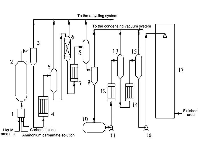
- Pre-reactor
- Urea synthesis reactor
- Pre-separator
- Medium-pressure circulation heater
- Medium-pressure circulation separator
- Distillation column
- Low-pressure circulation heater
- Low-pressure circulation separator
- Flash tank
- Urea solution storage tank
- Urea solution pump
- First stage evaporation heater
- First stage evaporation separator
- Second stage evaporation heater
- Second stage evaporation separator
- Molten urea pump
- Prilling tower
Desulfurization tower, Urea synthesis reactor, High-pressure mixer, Medium-pressure decomposition heater, Medium-pressure decomposition separator, Medium-pressure absorber, Ammonia condenser, Low-pressure decomposition rectification column, Low-pressure absorber (first & second carbamate condensers), Ammonia absorption tower
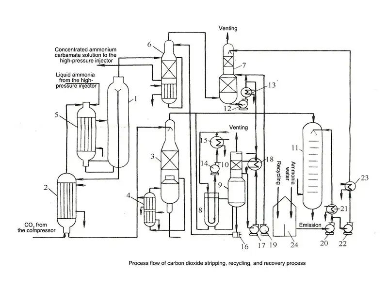
In the CO₂ Stripping Process, the urea synthesis solution flows into a stripping tower, where carbon dioxide gas flows counter-currently at elevated temperature. Steam heating on the shell side promotes the decomposition and desorption of excess ammonia and ammonium carbamate.
After stripping, the urea solution is withdrawn from the bottom of the tower, followed by gas-liquid separation. The resulting solution, primarily composed of urea and water, undergoes vacuum evaporation to achieve the desired urea concentration before final solidification.
- Urea synthesis reactor
- Stripping tower
- Rectification column
- Circulation heaters
- High-pressure carbamate condenser
- High-pressure scrubber
- Absorption tower
- Low-pressure carbamate condenser
- Level tank
- Absorber
- Analyzer column
- Absorber circulation pump
- Circulation condenser
- Circulation pump
- Cooler
- High-pressure carbamate pump
- Absorber circulation pump
- Absorber circulation cooler
- Flash tank cold liquid pump
- Analyzer column feed pump
- Analyzer column heat exchanger
- Absorption tower feed booster pump
- Top feed cooler
- Ammonia tan
The ammonia stripping process consists of the following main process sections:
- Carbon dioxide compression
- Liquid ammonia pressurization
- High-pressure synthesis and ammonia stripping recovery
- Medium-pressure decomposition and recycle
- Low-pressure decomposition and recycle
- Combined medium- and low-pressure recovery systems
- Vacuum evaporation and prilling
- Desorption and hydrolysis system
Delandi (Nantong) Machinery is dedicated to the development of the fertilizer industry, focusing on process design, production equipment manufacturing, and production performance improvement for fertilizer manufacturing projects. We bring together a team of experienced professionals with deep technical knowledge and long-term industry involvement.